

Print hydraulic flange parametric & 3D: bolt circle, hole pattern & pipe socket
You are looking for a Flange made to measure - without CAD? With our Flange configurator legst you Flange diameter, Thickness, Bolt circle / hole pattern, bores-Ø and Pipe ID/OD create the STL file and lässt den Print hydraulic flange 3D. Ideal for prototype, adapter flange, test arrangement or transition from hose to pipe.
What is it?
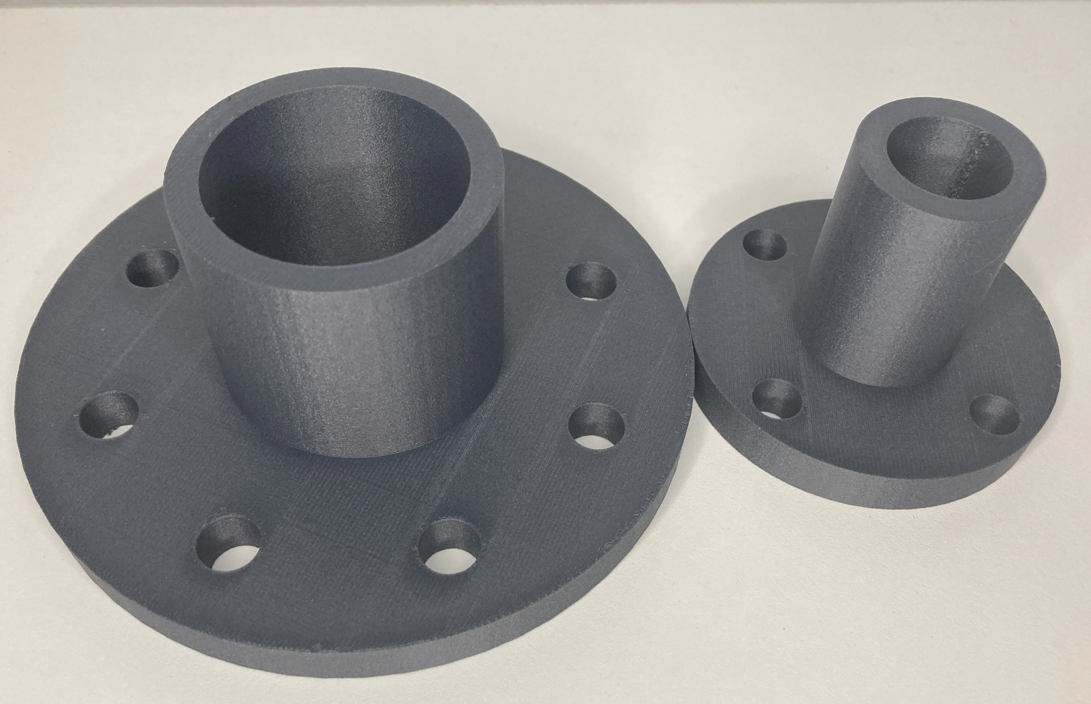
A hydraulic flange connects Tube, Pipe or Aggregate about a Hole pattern (bolt circle). The parametric flange creation is worthwhile if standard parts do not fit: adapterflansch, Transition flange, Reyouzierflansch, Sensor flange or prototype with custom pipe socket. Our Online-configurator creates a print-ready STL - fast, clean and without CAD.
You need these dimensions for parameterization
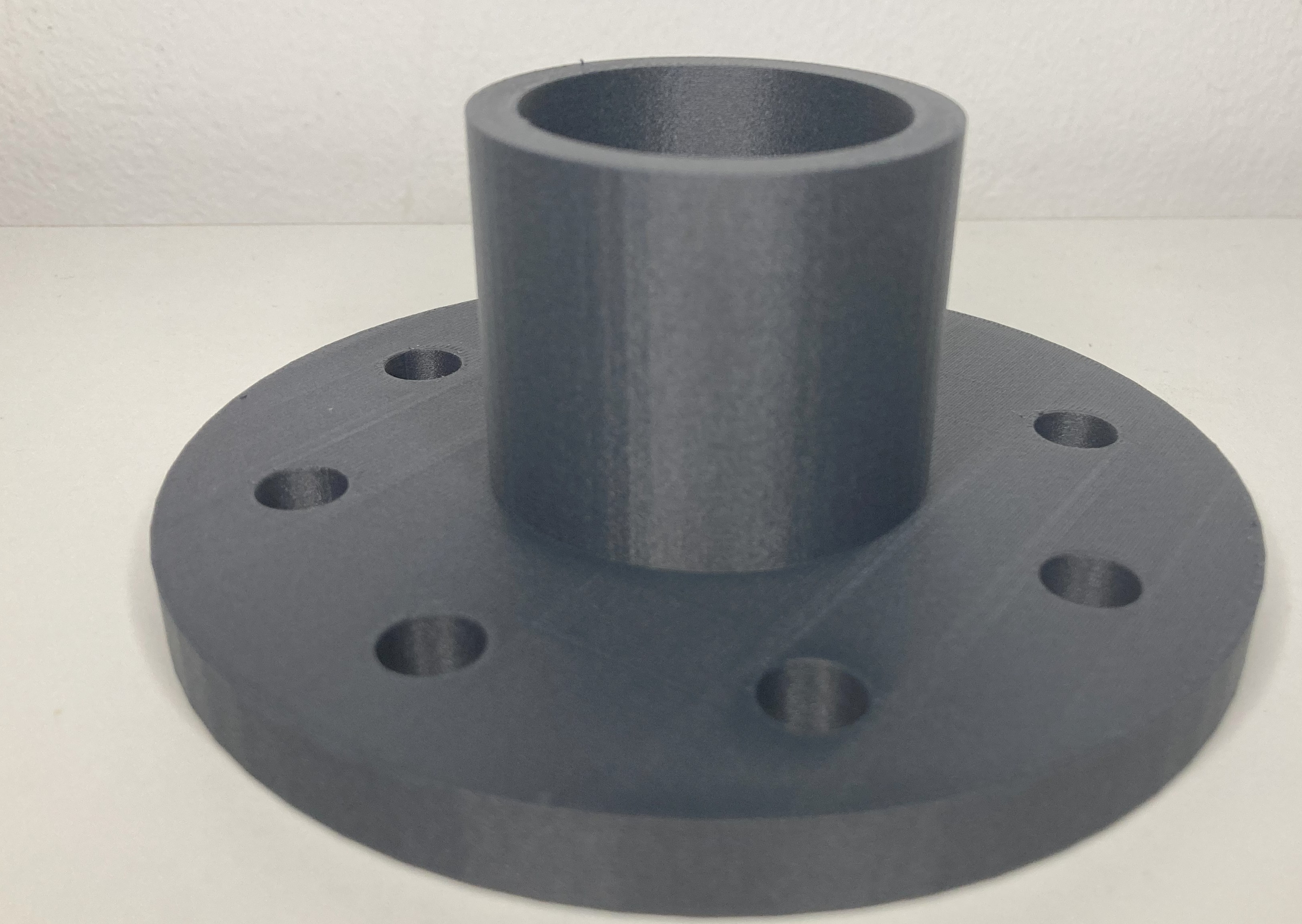
- Flange diameter (outer diameter) & Thickness - Installation space, stability, screw length.
- holekreis-diameter (BCD), number der boreen and bores-Ø - results in Drilling pattern.
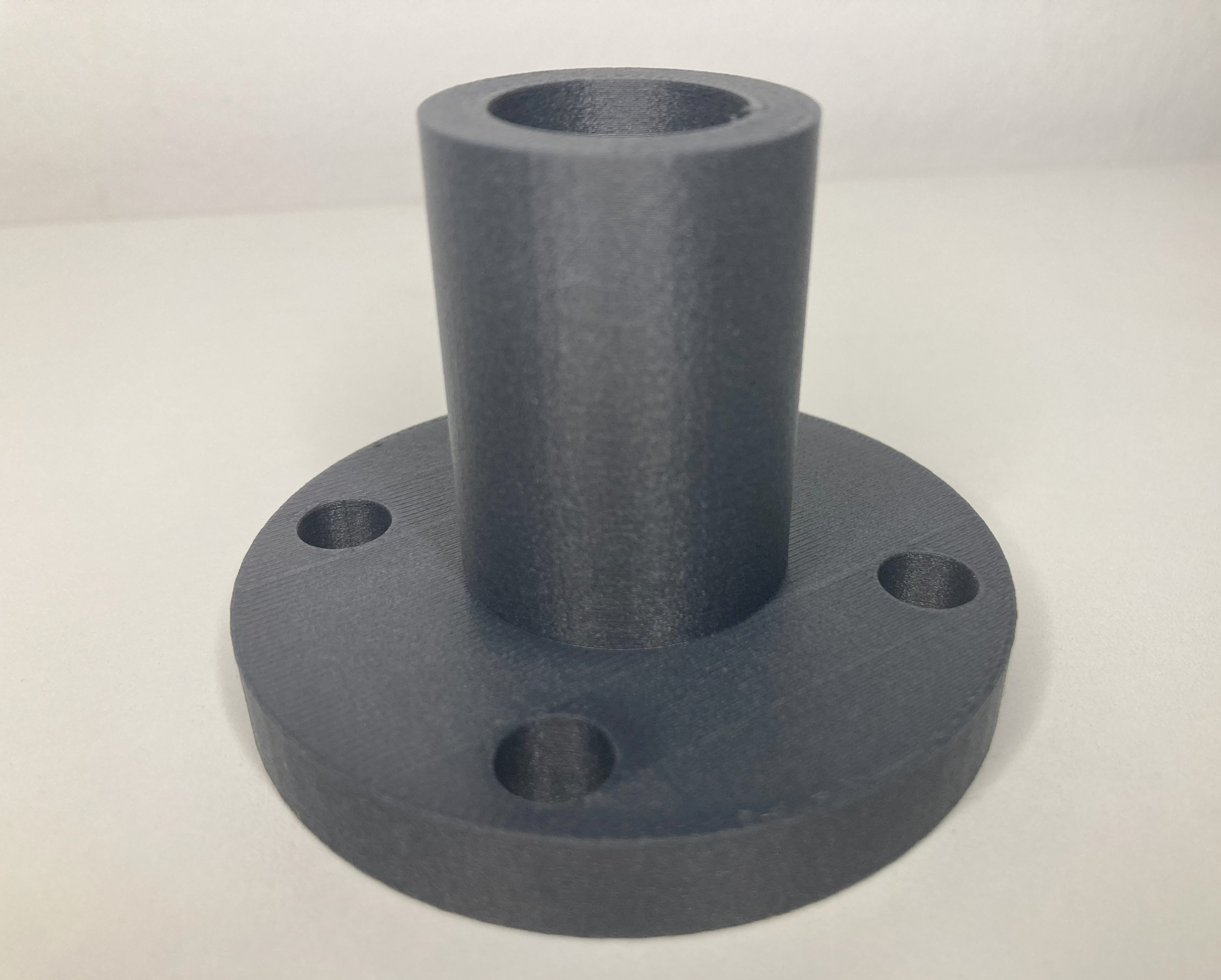
- Tube outer diameter (OD), Tube inner diameter (ID) and Tube length - define the Pipe socket.
Tip: Measure the mating flange with the caliper gauge. If you are unsure, start with conservative tolerances and a short test print.
Standard values & tolerances (bores, sealing surfaces, pipe)
| Feature | Guideline | Note |
|---|---|---|
| bores-Ø | Screw Ø + 0.2...0.6 mm | e.g. M6 → 6.4–6.8 mm (allow for printing tolerances) |
| Sealing surface | Layer height 0.12-0.20 mm | Print plan, fine sand / matt seal if necessary |
| Tube wall thickness | ≥ 2.0-3.0 mm | More perimeter increases tightness & stability |
| Centering | Centering collar / locating sleeves | Facilitates assembly, saves screws |
Note: Values for FDM-prototypes and Low pressure. For High pressure and safety-relevant We coordinate material, orientation and wall thicknesses individually with you.
Sealing concepts: O-ring, flat gasket, centering
- O-ring groove (rectangular or according to DIN dimensions): defined sealing line, repeatable.
- Flat gasket (e.g. fiber, rubber, TPU): tolerant to unevenness.
- Zentrierband and Fitting sleevessecure position, lower shear forces on screws.
Material selection & print settings
- PLA: prototype, Innenraum, sehr gute Detailtreue.
- PETGtougher, more temperature resistant - more versatile Allroander.
- ASA/ABSuV-resistant or robust - for outdoor & elevated temperature.
Settings: Layer 0.16-0.24 mm, 4-5 perimeter, infill 20-40 % (depending on load). Flange flat on the bed, pipe socket upwards - this ensures clean sealing surfaces.
Step-by-step: From the idea to the STL
- Measure the mating flange: bolt circle diameter, hole diameter, hole count, flange diameter and thickness.
- Choose the tube outer/inner diameter and length to match the medium and hose or line.
- Define sealing concept: O-ring groove, flat gasket, centering.
- Parametrisieren → preview checken → export STL.
- Order a 3D print – we deliver professional quality.
Also searched for:
Hydraulic flange 3D print, flange STL download, customized flange, bolt circle calculator, Calculate hole pattern, flange configurator online, pipe flange with pipe socket, Adapter flange 3D print, custom flange 3D print, bolt circle calculator.
FAQ
How accurate is the drilling pattern from the configurator?
Tolerances in the tenths range are realistic for FDM prints. Select bore Ø slightly over screw Ø to obtain assembly clearance.
Replacement for standard flanges (DIN/EN)?
We manufacture to your exact specifications. For standard-compliant applications, please contact us - we will check drilling patterns/dimensions and advise on suitable Process/Materials.
Can I switch to metal later?
Yes, use 3D printing for prototype & testing; upon approval we can Derive drawings for CNC/metal construction.