

Reverse engineering & surface reconstruction — create a CAD model from a 3D scan, STL or mesh
You only have one 3D-Scanone STL filea Mesh or a Point cloud - but no editable CAD model? Right here comes Reverse Engineering into play. Through professional Surface Reconstruction are created precisely from scan data CAD-modelewhich is responsible for design, production, simulation, Spare parts and product development.
Whether STL to CAD, Mesh to CAD, 3D-Scan to STEP or Scan zu CAD-modelwe support the digital reconstruction of components for industry, Mechanical engineering, repair, prototypes and 3D printing.
Jump directly to:
What is it?
Reverse Engineering means that an existing component is digitally analyzed and reconstructed. Unlike a classic new design, you don't start with an idea at the CAD workstation, but with an existing part, a scan, a STL file or a mesh.
The aim is to use this data to präzises, nutzbares and bearbeitbares CAD-model to create a model. This model can then be used as STEP, STP, IGES or in another agreed format.
Reverse engineering is particularly needed when:
- original CAD data are no longer available,
- a spare part needs to be reproduced,
- an existing component needs to be optimized,
- a scan is to be converted into an editable design model,
- an existing product needs to be digitized.
What is it?
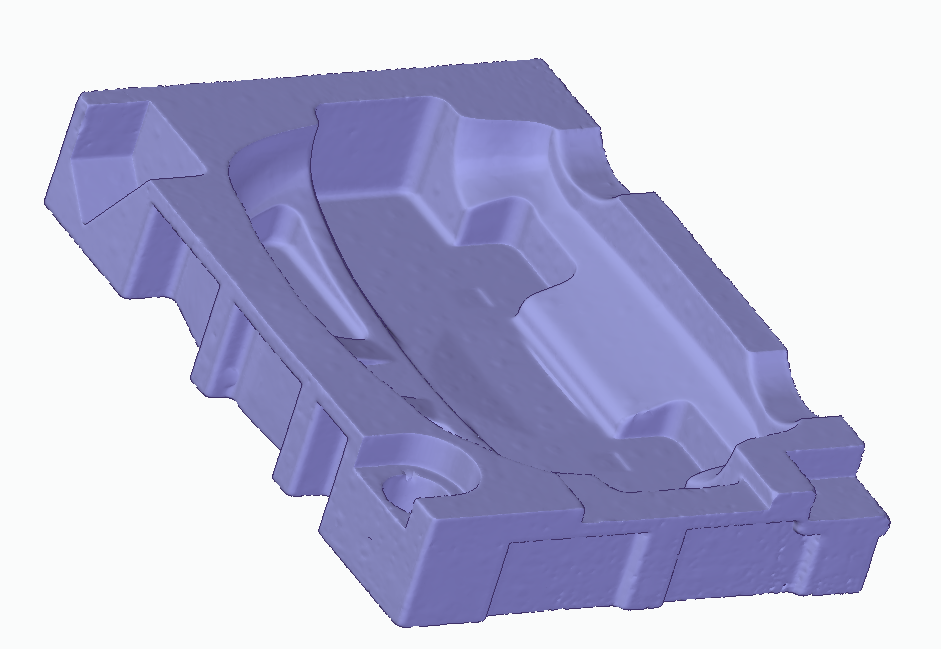
The Surface Reconstruction is a central part of reverse engineering. In this process, unstructured or polygonal data - for example from a STL filea Mesh or einem 3D-Scan - converted into defined technical areas.
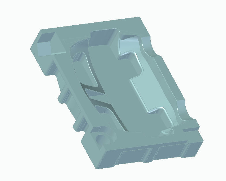
A STL consists only of many small triangles. This geometry is often sufficient for 3D printing, but for technical design, dimensional changes, parametric editing or clean development only suitable to a limited extent. By contrast, reverse engineering produces mathematically described NURBS surfaces or other CAD-compatible geometries.
In concrete terms, this means
- from STL to CAD becomes an editable model,
- from Mesh to CAD creates a technical basis for design,
- from 3D-Scan to CAD a model for manufacturing, testing or optimization.
Benefits of reverse engineering and surface reconstruction
Reverse engineering is always worthwhile if a component exists, but the design data is missing or cannot be reused. The most important advantages:
Technical advantages
- Create CAD data from existing parts
- STL, Mesh or Scan in STEP / IGES umwandeln
- Precisely analyze and develop components
- Making geometries usable for design and manufacturing
Practical advantages
- Reproduce spare parts when no design data remain
- Digitize old components
- Improve or adapt products
- Have scan data professionally analyzed
What kann man with Reverse Engineering machen?
Many people search Google for terms such as spare part nachbauen, convert STL to STEP, convert 3D scan to CAD or Convert Mesh to CAD. This is exactly what reverse engineering is used for.
- spare parts rekonstruieren: When the original manufacturer’s part is no longer available
- Mechanical engineering: Bestehende Komponenten digitalisieren and dokumentieren
- Automotive sector: Reconstruct old or hard-to-find components
- Product development: Reuse and develop existing shapes
- 3D printing: Convert scan data into technically usable models
- Quality and inspection: Evaluate geometries and compare them with target dimensions
- Tool and mold making: Bestehende Geometrien reproyouzieren
What data is required for reverse engineering?
Perfect data is not always necessary for a request. Just a good STL file, a usable 3D scan or a mesh may be sufficient. Typical input data are:
- STL file
- OBJ-file
- PLY-file
- 3D-Scan-Daten
- Mesh files
- Point clouds
- Fotos with Referenzmaßen
- Drawings or dimensions, if available
The better and more complete the initial data, the more efficiently generate the desired CAD model. Even incomplete data can be can often be meaningfully evaluated and supplemented.
What does the customer get in the end?
The aim is not just a visual reconstruction, but a technically usable result. Depending on the project, the result can be, for example:
- CAD-model als STEP / STP
- CAD-model als IGES
- technically optimized surface models
- Geometry for further processing in CAD systems
- Data for design, manufacturing or 3D printing
This is how a request works
- Upload file: STL, Scan, Mesh, Punktewolke or Bilder senden
- Check the data: Assess geometry, quality and effort
- Get a quote: usually within 24 hours
- Release: processing starts after confirmation
- delivery: CAD data in customized format
Request reverse engineering now
Upload your STL, mesh or scan file conveniently via our form. As a rule, you will receive an invoice within 24 hours a quote.
For whom is reverse engineering interesting?
The service is of interest to companies, workshops and private customers who want to make existing components digitally usable.
- Mechanical engineering
- Instandhaltung and Reparatur
- Automotive
- Toolmaking
- Product Development
- 3D printing and prototypeing
- private customerskanden with spare partbedarf
FAQ - Reverse engineering & reverse engineering
Can any STL file be converted into a CAD model?
Basically very often yes, but the effort depends heavily on the quality, Completeness and complexity of the geometry. Simple technical parts can usually be reconstructed more quickly than organic or badly damaged shapes.
What is it?
A STL describes the surface over many triangles and is mainly intended for 3D printing. A CAD model has a constructive structure, is technically editable and can be used for modifications, manufacturing and Further development much more suitable.
Which formats can be supplied?
We often deliver STEP, STP or IGES. Depending on the application, other CAD-compatible formats can be agreed.
How quickly can I get a quote?
After uploading your data via the request form, you will usually receive a quote within 24 hours.
When is worthwhile Reverse Engineering besonders?
Reverse engineering is particularly useful when CAD data is missing, when spare parts are no longer available, when digitizing existing components and whenever a scan is to be further processed technically.
Request reverse engineering now
You already have a STL file, a 3D scan, a mesh or photos with dimensions? Then send your data now using the form. You will usually receive within 24 hours a quote.